About a year ago, on a sound engineer job at a community house, I came across an old tube amplifier in the attic. Seemed like it belonged to a movie projector system, probably built in the 1960s. Power and signal cables on side terminals were cut. It was quickly inspected before I nicked some of its tubes and put it back where I found it. I’ve been thinking of this amp since, wondering what kind of amp this could be modified into.
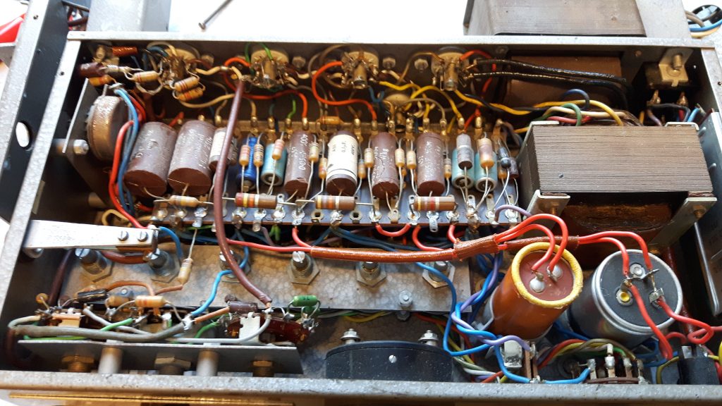
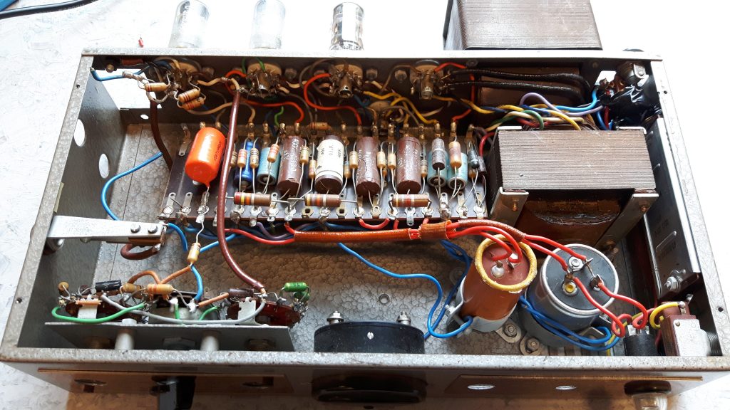
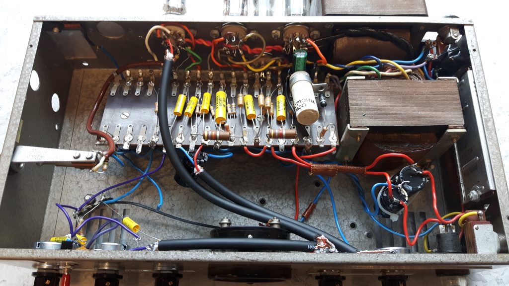
I was back at that community house in early February on another sound engineer job. I met the guy in charge of the technicalities of the house and asked if I could have this amp; I was free to grab it. He told me it had been in use for the last time in the early 80s. I brought it back to my work headquarter and removed the top cover, found a pen and paper and started tracing and sketching the circuit.
Information about the amp:
Built by Hans H. Knutsen & Co, Oslo, Norway. No brand/model name on the amp itself, but saw that name on other movie projector equipment in that attic. Six-pin modular sockets on the left and right rear edges, probably for easy amp swapping. Two EL84 power tubes, two EF86 and one ECC83 in the preamp. All Telefunken tubes from around 1963. Siemens selenium rectifier. Input jack on the left side and terminal inputs for left machine, right machine and line on the rear left modular socket. Volume control, tone switches, speaker output jack and meter/switch for checking tubes and output voltage on the front. Speaker output and power input on the rear right modular socket. Screwdriver trim pots on the left side for adjusting DC for left and right machine photocell pickups. Output power: 10-15 watts.
Signal path: Left machine/right machine/jack inputs -> first EF86 as triode stage -> line input -> tone/volume controls -> second EF86 as pentode stage -> direct-coupled ECC83 LTP phase inverter -> cathode-biased EL84 output tubes -> ultra-linear output transformer -> speaker outputs (taps measured to ~6 and ~16 ohms). Negative feedback from the 16 ohm tap through an RC network into the cathode of the second EF86 stage. The circuit between the volume/tone controls and the output transformer is pretty similar to the Mullard 5-10.
This amp can be modified into many uses, but my primary goal was to make a low-watt bass amp for practice and recording. I have used my Epiphone Valve Jr for this, but I’ll mod that one for pure guitar use rather than guitar/bass use.
The first task was removing the tube voltage monitoring and input DC adjusting circuits. This operation made the crowded chassis somewhat tidier and freed some space on the left end of the eyelet board. I also checked the fuse on the front-right edge. The holder was marked “2A”, but there was a 6A fuse installed. I replaced it with a 1A fuse. I also connected an IEC power socket with proper grounding. Ready for connecting power, speaker and electric guitar for the very first test.
I turned the amp on and crossed the fingers for no magic smoke escape anywhere. The tubes got warm and I heard a little 50 Hz hum from the speaker. Turned up the guitar volume and played a little. I got sound, but a rather ugly distortion as I advanced the volume beyond 9 o’clock. Did voltage measurements here and there and found that some caps leaked DC, including the coupling caps between phase inverter and power tubes. This messes up the power tubes’ biasing, creating bad distortion at best and killing them at worst. First priority was swapping these old and leaky capacitors.
I didn’t have any replacement caps around, just a few recycled from old electronic equipment and not suitable for tube amp voltages. I had ordered a capacitor value pack and various other components some days earlier, but it took quite some time before the shipment arrived. I had a few waiting days before getting the amp into working order. During these days I removed both the modular sockets on the back sides. I installed an IEC mains socket from an old PC power supply that just fit the modular socket hole with some adjustment. I also moved the speaker output jack from the front to the back, above the power socket. I also simplified the speaker signal and ground wiring in the process.
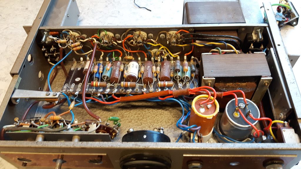
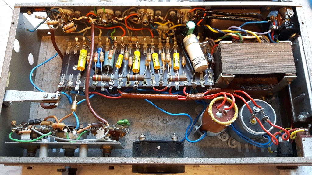
The shipment with components finally arrived, including a value pack of Mallory 150 630V caps between 1 and 100 nF. Time for removing the old, leaky and cracked Hunts caps and soldering the new Mallorys in. Turned the amp on with a dummy load to check voltages, seemed normal. Tried it with a speaker and made it play rather loud before distorting. Noticed that the second EF86 stage was quite microphonic. Got a bit of feedback that continued even with the volume turned to zero. The next task was changing the EL84 cathode resistors and bypass caps. The two resistors measured different values and one of them seemed a bit burned. The caps had leaked some electrolyte. Measured the plate dissipation, it was 76% for one tube and 99% for the other, a bad imbalance. Removed them all and installed a common 150 ohm 10W power resistor with a 680 uF cap across it for stiffer bass response. Voltages seemed OK, the tubes ran at 98% plate dissipation. Just where I want it; max output without pushing the tubes too far.
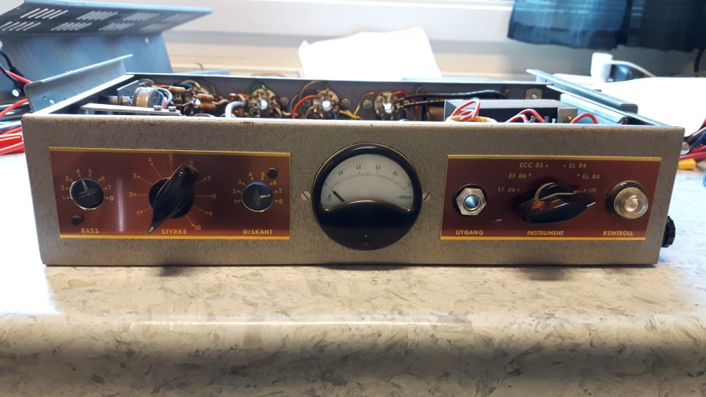
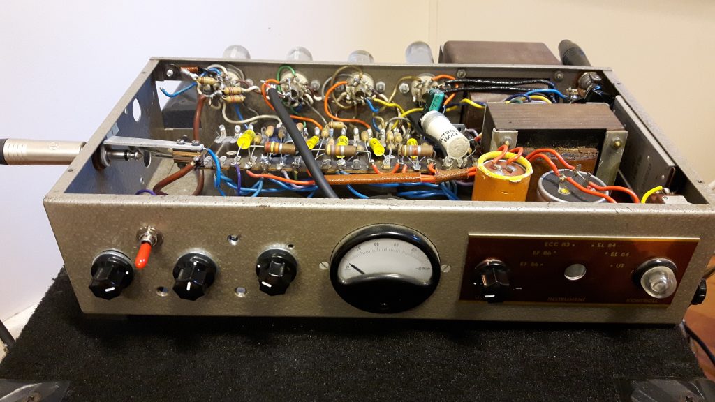
The stock tone controls were James-like 8-way bass and treble switches that had to be manipulated with a cross-head screwdriver. Too awkward for normal use. Removed the whole shebang and installed new James tone controls with Ampeg component values. In addition to bass and treble I added a pot for shifting the midpoint between them, adjustable between about 150 Hz and 1 kHz. I also added a switch for a boost around 200 Hz. There were just three holes on the front left side, so I put the gain control at the right side of the meter where the speaker output used to be.
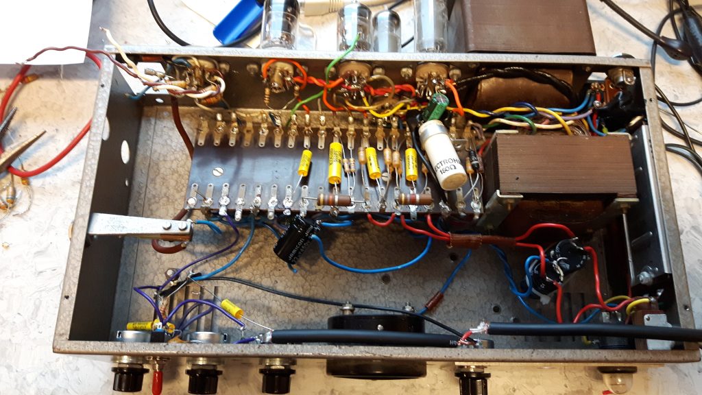
One task is important on old amps: Replacing the electrolytic caps in the power supply. I had a few recycled ones with 400-450V rating, so I swapped the two can caps with these. The B+1 and B+2 caps were mounted with a screw, a nut and a couple of cable ties. I soldered the last two caps directly to the eyelet board.

A working power section, proper tone controls and far newer electrolytic caps. Time for plugging in a bass and testing the amp. Tone controls worked like they should, but I noticed three negative things with the original 2x EF86 preamp: Too much gain, too much mains hum and seriously microphonic second stage. Heard the ringing just by plugging a cable into the jack. According to the EF86 data sheet, the stage component values gave an amplification factor of 170x. Way too brutal. Buzzy distortion already at 10 o’clock on the volume control. Tried removing the second stage cathode bypass cap. That tamed the gain a bit, but still mains hum and microphonic EF86 tube. This amp needs a redesigned preamp section!
Back to the drawing board. Decided to take the following route: Two ECC83/12AX7 gain stages with the tone and gain controls between them and a volume control in the end before hitting an AC-coupled LTP phase inverter instead of the original direct-coupled one, using the original ECC83/12AX7. One tube less than the original preamp circuit. Picked the phase inverter component values with assistance from The Valve Wizard.
As I removed the original preamp components, I also swapped some of the tube sockets. They were old and loose, particularly the two EL84 sockets. I only had three 9-pin sockets laying around, so I replaced the power tube and phase inverter sockets. Preamp tube socket got replaced later. I re-did the heater circuit with tightly-twisted wires for minimal hum. There wasn’t much space between the eyelet board and the rear wall, so it was a rather fiddly operation. Then it was time for wiring up the phase inverter. Tested it by attaching signal from a Tech 21 Blonde pedal via alligator clips. Seemed to work, and voltages were within the ballpark. Next was installing a master volume pot, wire up the preamp section and remove the unused tube socket. Plugged it in, turned it on and played. Worked. I used the following tubes in the amp: Mesa-branded Ei 12AX7 for the preamp, the original Telefunken smooth-plate ECC83 for the phase inverter and JJ EL84 power tubes. One original Telefunken EL84 went into the Epiphone Valve Jr, the other one and the two EF86es reside in my spare tube drawer.
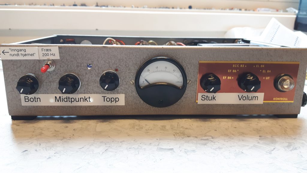
One last thing was remaining. The large meter in the front just can’t sit there without a function. Found a pot and clipped it in between the stock diode at the NFB tap and the positive meter terminal. Adjusted until the needle struck the other side when the power amp distorted. Measured the pot resistance and soldered in an approximate resistor for a working Ashdown-style VU meter.
Forthcoming tasks: Make a better front panel design. Swap the last tube socket. Add some tube protection in the rear. Avoid the BUMS (“Blind Urge to Mod Syndrome”) phenomenon by realizing that this circuit works and that endless mods for “improvement” probably are useless.
This project is inspired by Brad “The Guitologist” Linzy. He’s an expert in troubleshooting, restoring and modifying old tube amps and has published lots and lots of YouTube videos of his projects. I’ve also been reading the pages on the Valve Wizard site several times to learn various technicalities and make design choices.
Edit 03/02/2018:
I needed to make one change. Didn’t get any preamp grind, even with gain all the way up. Tried boosting the preamp B+ from 260 to 290 V, no change in sound. Tried adding a cathode bypass cap to the first 12AX7 stage, but still didn’t get any grind. Changed the signal path into this: 1st gain stage -> gain pot with bright switch -> 2nd gain stage -> tone stack -> volume pot -> phase inverter. Near-identical to the Ampeg B25 preamp section. This gave quite a bit of preamp overdrive with gain turned up.
Edit 03/12/2018:
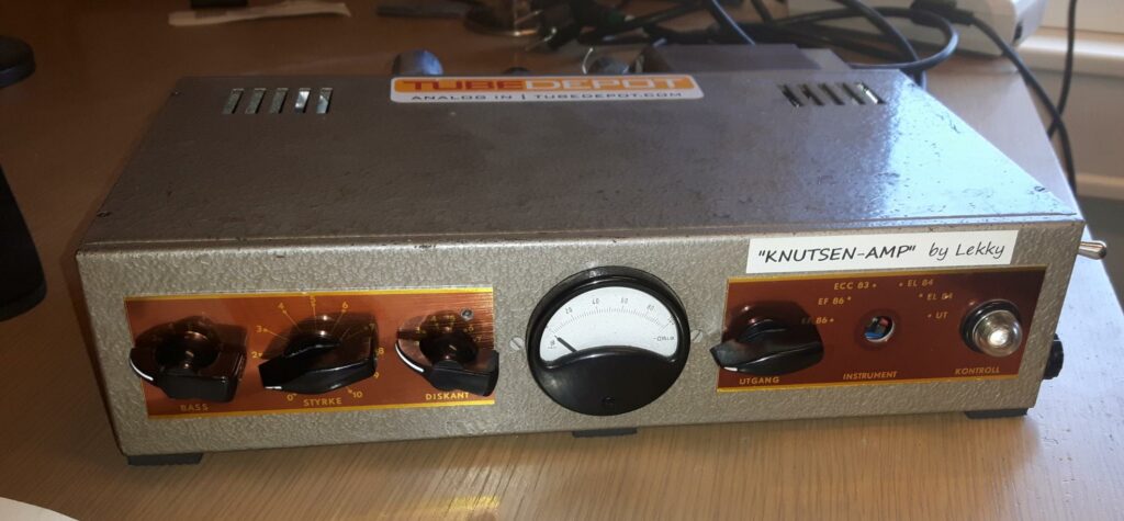
I checked the output transformer secondary taps again, measuring PROPERLY rather than my half-assed attempt earlier. Injected 9V AC into the secondary sides and measured the primary side instead of the other way around. The two taps were 16 and 6 ohms into 8k primary. I also fit an impedance switch between the power socket and speaker jack. Front panel labels have been remade properly as well – and it’s named “Knutsen-Amp” after the Hans H. Knutsen company that built it: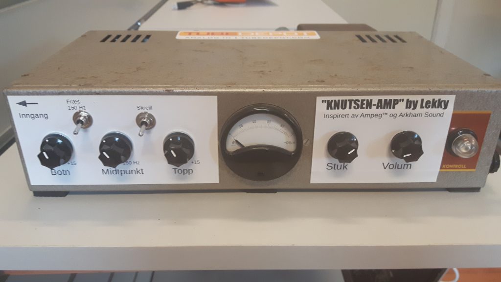
Edit 10/06/2018:
I just couldn’t keep my hands off the innards of this amp, in the quest of more clean output. Swapped the 150 ohm bias resistor for two serially-linked recycled resistors for ~175 ohm to reduce the plate dissipation a bit. I later removed the selenium rectifier and installed a silicon bridge rectifier. The first B+ node increased from ~340 to ~380 V, and I had to change the EL84 cathode resistors again into three recycled resistors combined at ~210 ohms. Clean sinewave output increased from ~9 to ~12 W. Put the Telefunken EL84s back for a slight increase in clean headroom compared to the JJs. I later went back to the stock setup with separate cathode resistors and bypass caps, going for 2x 470 ohms/3W and 2x 220uF/50V. The two Telefunken tubes are slightly unbalanced, but it evened out a bit with separate cathode resistors compared to shared.
Did another couple of mods too: The low-mid boost switch got replaced with a three-way switch, giving two boost options: “Rammel” (~200 Hz) and “Rommel” (~80 Hz). I also added a line-out from the cathode of the second preamp stage, placed at the rear left side where the photocell voltage trimmers used to be.
Inspired by this video by Uncle Doug, I decided to remove the shabbily-mounted rear connectors and switch and put back the stock six-pin male connector. Made a connection module with the female connector, two speaker jacks and an attached mains power cable. The amp is now DONE. Period. I promise. Nothing more to mod! 🙂
Edit 2021:
I dug out the left side stock panel with the labels “Bass”, “Styrke” (loudness) and “Diskant” (treble) from a parts bin. The white labeling isn’t all that beautiful, so I decided to peel it all off and reinstall that panel. The midpoint-shift control and the two switches had to go, and the gain control got moved to the middle left position. Goodbye Arkham Sound-style extra controls, hello simplicity and better looks. Put the two original chickenhead knobs back on the gain and master controls and two newer chickenhead knobs for the bass and treble controls: